FAQs
Earthing FAQs
Why is specialist earthing design important?
- Correctly designed and installed earth electrode systems are essential for the correct operation of equipment and to ensure the safety of people
- The effects of touch and step potentials can be dangerous to people and livestock too
- Accurately designed earthing systems ensure that the safe voltage limits (defined by the duration of the fault and the local ground covering) are not exceeded
What is touch potential?
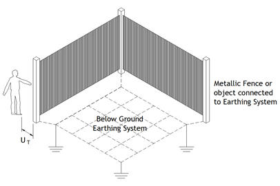
- Touch potential is the voltage between conductive parts when touched simultaneously; either between hands, or between hands and feet
- An example of this would be a person touching metalwork, such as a metallic fence whilst their feet are in contact with the ground beneath, at the same time that an electrical fault or lightning strike occurs; and is discharged into the earthing system

What is step potential?
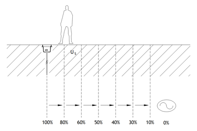
- Step potential is the voltage that can exist between two points (normally a person’s feet, as they step) on the earth’s surface; measured at a one metre interval, which is considered to be the stride length of a human
- An example of this might be a person walking over, or near to an area containing an earthing system; at the same time that an electrical fault or lightning strike occurs; and is discharged into the earthing system

What is transferred potential?
- Transferred potential is the voltage rise of an earthing system caused by an external fault transferred to the earthing system by a connected means such as cable sheaths, metallic pipework etc.
What is a “cold” site?
- The definition of a “cold” site is defined by the International Telecommunications Union (ITU); where the Earth Potential Rise (EPR) limit is 430V for a fault clearance time in excess of 200ms and 650V for fault clearance times equal to or less than 200ms
What does measuring soil resistivity involve?
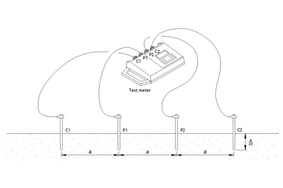
- Soil resistivity measurements (Wenner method) involve the use of a four-pole test instrument, such as a Megger DET2/2
- Four equally spaced test earth electrodes are inserted in the ground to a maximum depth of 200mm and each is connected to the test instrument with a separate lead
- After each measurement is recorded the distance between the electrodes is increased, from a short distance of 1m, up to much larger distances dependent upon the space constraints of each site

How often should an earthing system be tested?
- Omega recommends that driven earth electrodes are tested annually and the values compared to those previously obtained
- Significant variations in results should be investigated and any remedial works carried out
- The overall resistance of a whole earthing system should be measured at five-yearly intervals, using the ‘Fall of Potential’ test method, and the results compared to those previously obtained
How should below ground earth connections be made?
- Omega recommends that all buried connections between copper tapes are made using oxy-fuel (Sil-Fos®) brazing techniques
- All connections to driven earth electrodes should be made using exothermic welding techniques
- Omega also recommends that cable to cable connections are made either by exothermic welding or compression joints
Lightning protection FAQs
What is the British standard for lightning protection?
- The British standard for lightning protection is the current edition of BS EN 62305 – Protection against lightning
- It is the British edition of the European standard (both are derived from IEC 62305) to which all lightning protection systems to new structures, and new extensions to existing ones, are designed, installed and maintained
- BS EN 62305 was first introduced in 2006 and replaced BS 6651:1999 from 1st September 2008
- New versions of Parts 1, 3 and 4 of BS EN 62305 were issued in 2011; followed by a new version of Part 2 in 2012
Is a lightning protection system required?
- A lightning protection system is required if it is determined that there is sufficient risk of a lightning related event causing harm and damage to a structure, the people in and around it and the systems on and within it
- The need for protection and the economic benefits of selecting and installing adequate protective measures should be determined in terms of risk management (by assessment)
- However, the decision to provide a lightning protection system can be taken regardless of the outcome of risk assessment, where there is a desire that there be no avoidable risk; or where protection against lightning is required by the authority having jurisdiction
What are the component parts of a lightning protection system?
- The component parts of a lightning protection system are the external:
- air termination system – this intercepts a lightning flash
- down conductor system – this conducts the lightning current to earth
- earth termination system – this disperses the lightning current into the earth
- Plus primary internal protection measures, such as equipotential bonding, to prevent dangerous sparking and the ingress of lightning currents, via cables and services
- Additional protection measures can be used to reduce the risk of damage to electrical and electronic systems from the effects of lightning electromagnetic impulse (LEMP)
- These include:
- Earthing and bonding
- Magnetic shielding
- Line routing
- Isolating interfaces
- Coordinated transient over-voltage SPDs
Are all lightning protection systems the same?
- All conventional lightning protection systems follow the Faraday Cage principle of creating a protected volume around an object (structure) or an area considered to be at, or containing items at, risk from lightning related events
- There are two fundamental types of lightning protection system
- An isolated lightning protection system is where components are separate from, and arranged so as to create a volume within which, the protected object or area is located; and where these are physically and electrically isolated from each other
- A non-isolated lightning protection system is where components are arranged on, and sometimes form part of, the object to be protected; and where these are not physically and electrically isolated from each other
How often should a lightning protection system be tested?
- Lightning protection systems should be periodically inspected and tested in accordance with the requirements of the British standard in force at the time of the original installation; at a point in time when an existing system was either reassessed, amended or upgraded
- If the above is not known then the current British standard should be used
- Currently, this is carried out on an annual basis
Will Brexit affect the compliance of my lightning protection system?
- No, as the United Kingdom will remain part of CENELEC and the wider IEC technical committees, irrespective of what happens
- Omega has representation on National (BSI), European (CEN) and International (IEC) Technical Committees
Surge protection FAQs
What are surges?
- Surges are high magnitude voltage peaks of only microseconds duration
- Direct and indirect lightning strikes are the most common source
- They are also created with the switching of large inductive or capacitive electrical loads within buildings
What do surge protection devices do?
- Surge protection devices perform two functions; they divert partial lightning currents and limit transient overvoltages
- Both can be as a result of lightning activity
Do surge protection devices have to be installed?
- Surge protection devices are required wherever there is a BS EN 62305 structural lightning protection system and where there are services that enter or leave a structure
- They are also required where it is necessary to protect electrical installations against transient overvoltages of atmospheric origin transmitted by the supply distribution system; as described in BS 7671
- Surges can be the result of direct lightning strikes to the power distribution system and where switching overvoltages are generated by equipment within an installation
Do surge protection devices need testing?
- Surge protection devices should be inspected and tested as part of the overall lightning protection inspection and testing regime
- Low voltage power SPDs should also be inspected as part of the periodic inspection and testing requirements of BS 7671
Can different manufacturers’ SPDs be installed on the same project?
- It is perfectly acceptable to use different manufacturer’s surge protection devices on the same project, providing that the designer of the system takes account of the parameters involved
Can Omega install surge protection devices?
- Omega engineers have the competence and experience to install surge protection devices
- Our SMSTS and City & Guilds 2382-18 trained engineers have the knowledge and experience to install surge protection devices; in a safe, competent and efficient manner
Is it possible to retrofit surge protection devices to an existing installation?
- Surge protection devices can be installed to all existing electrical power and data systems, irrespective of their age
- Omega engineers can carry out detailed site surveys to assess any surge protection requirements and provide reports detailing a best-engineered solution
- Omega engineers have the competence and experience to install all surge protection devices, to an existing installation
