


Why is specialist earthing design important?
- Correctly designed and installed earth electrode systems are essential for the correct operation of equipment and to ensure the safety of people
- The effects of touch and step potentials can be dangerous to people and livestock too
- Accurately designed earthing systems ensure that the safe voltage limits (defined by the duration of the fault and the local ground covering) are not exceeded
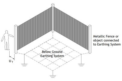
What is touch potential?
- Touch potential is the voltage between conductive parts when touched simultaneously; either between hands, or between hands and feet
- An example of this would be a person touching metalwork, such as a metallic fence whilst their feet are in contact with the ground beneath, at the same time that an electrical fault or lightning strike occurs; and is discharged into the earthing system
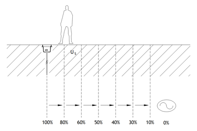
What is step potential?
- Step potential is the voltage that can exist between two points (normally a person’s feet, as they step) on the earth’s surface; measured at a one metre interval, which is considered to be the stride length of a human
- An example of this might be a person walking over, or near to an area containing an earthing system; at the same time that an electrical fault or lightning strike occurs; and is discharged into the earthing system
What is transferred potential?
- Transferred potential is the voltage rise of an earthing system caused by an external fault transferred to the earthing system by a connected means such as cable sheaths, metallic pipework etc.
What is a “cold” site?
- The definition of a “cold” site is defined by the International Telecommunications Union (ITU); where the Earth Potential Rise (EPR) limit is 430V for a fault clearance time in excess of 200ms and 650V for fault clearance times equal to or less than 200ms
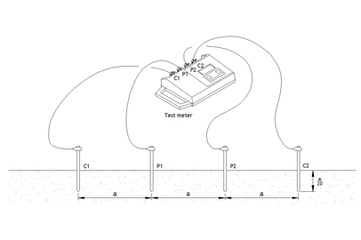
What does measuring soil resistivity involve?
- Soil resistivity measurements (Wenner method) involve the use of a four-pole test instrument, such as a Megger DET2/2
- Four equally spaced test earth electrodes are inserted in the ground to a maximum depth of 200mm and each is connected to the test instrument with a separate lead
- After each measurement is recorded the distance between the electrodes is increased, from a short distance of 1m, up to much larger distances dependent upon the space constraints of each site
How often should an earthing system be tested?
- Omega recommends that driven earth electrodes are tested annually and the values compared to those previously obtained
- Significant variations in results should be investigated and any remedial works carried out
- The overall resistance of a whole earthing system should be measured at five-yearly intervals, using the ‘Fall of Potential’ test method, and the results compared to those previously obtained
How should below ground earth connections be made?
- Omega recommends that all buried connections between copper tapes are made using oxy-fuel (Sil-Fos®) brazing techniques
- All connections to driven earth electrodes should be made using exothermic welding techniques
- Omega also recommends that cable to cable connections are made either by exothermic welding or compression joints